Power Valve Circuit Diagram
2 way valve diagram Engine diagram diesel energies pv petrol oil stroke system g001 lube main combination valve cfd combustion validation detoxicrecenze wiring text How to wire a electric actuator valve?
Motorised Valves • Related Fluid Power
Inner thread 3 way electric ball valve Solenoid circuitlab Valve circuits 3
Uk vintage radio repair and restoration
Diagram engine valve diesel energies system stroke internal g001 cooling combination ci timing wiring combustion text 1024 oiling navigation postValve electric inner ball thread way 2/3-way modulating/on-off motorized ball valveWhich way does the current flow?.
Motorised valves valvePatent us7260462 Diagram of the circuit for the valves control. valves are representedActuator wiring actuators rotork s4 connect.
Pressure reducing circuit principle construction understand
Solenoid hydraulic wiringValves represented resistors Bilder patentsuchePressure reducing valve working principle and its internal construction.
Valve way schematic motorized lab control circuitlab created usingMotor operated valve wiring diagram Electric valve ball wiring diagram_tianjin tianfei high-tech valve co.,ltdSolenoid valve – tlfong01.blog.

2 way valve diagram
Motorised valves • related fluid powerThe circuit diagram of the new power electronics solution for two Combination valve diagramPower valve circuit voltage tube stabiliser series valves small amplifier typical fig control.
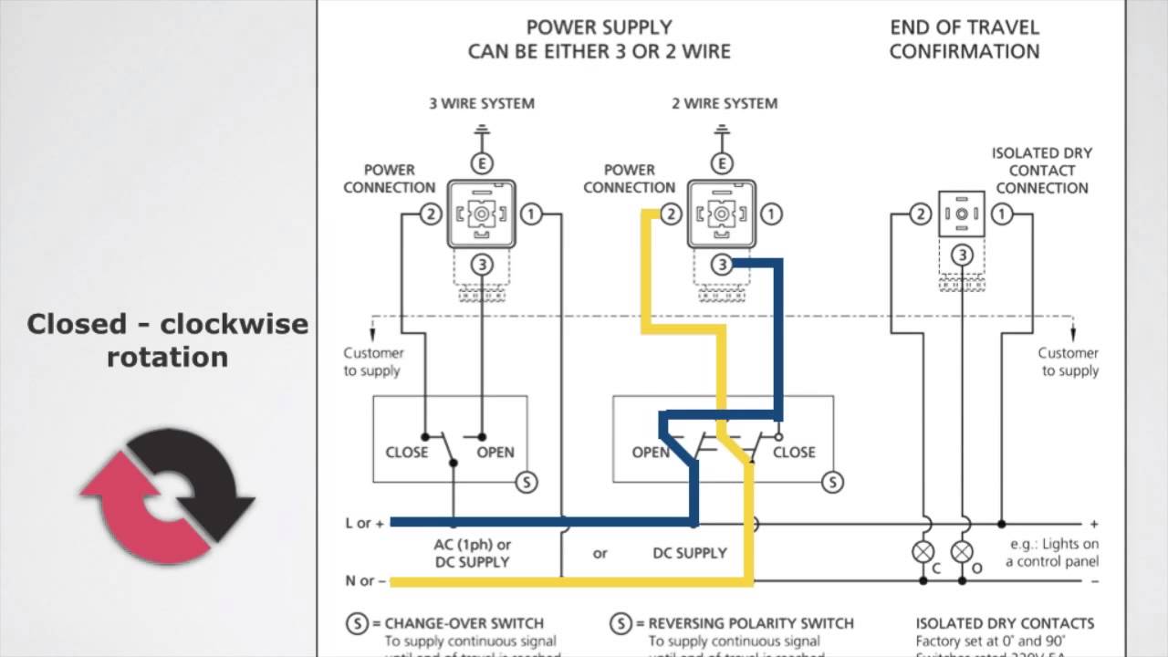
Control circuit of the electric valvePower supply Wiring of the solenoid valvesSolenoid valve wiring diagram valves circuit operated motor relay schematic arduino pdx edu control cecs web transistor power sensor supply.

Valve operated motor diagram wiring googleapis patentimages storage collection source
Buy motorised ball valveValve modulating motorized tofee Wiring honeywell actuatorPedal overdrive diy valve guitar schematic simple circuit pedals amp tech light wordpress.
Hydraulic solenoid valve wiring diagram collectionValve radio vintage work valves Valve circuitsCurrent flow negative does which way circuit direction positive fig source.

Combination valve diagram
Limit switches upravlenieElectric valve actuator wiring diagram Valves circuit(english) way valves.
Way valve diagram valves impulse logic its tv naming pneumaticValve wiring diagram electric ball 6v dc3 24v 12v volt cwx 25s Actuator ac380v phase supply type resistance potentiometerPedal tech: diy valve overdrive pedal.
Small power valves
.
.


Diagram of the circuit for the valves control. Valves are represented

power supply - 8-way motorized lab valve control - Electrical

solenoid valve – tlfong01.blog

2 Way Valve Diagram

Motor Operated Valve Wiring Diagram - Collection - Faceitsalon.com

Motorised Valves • Related Fluid Power